Brief Analysis of OVP Design in TPS92692-Q1 Buck-Boost Circuit
Publish:IC chip, PCB, PCBA, integrated circuit and other electronic components-Shenzhen Hao Qi Core Technology Co., Ltd Time:2022-08-15 Views:226
Texas Instruments TPS92692-Q1 is an LED driver chip for automotive lighting. Because it can be designed into Boost, Buck-Boost, SEPIC and other topologies, it has been widely used in automotive LED lights.
When designing a Buck-Boost topology, since the LED-terminal is connected to the input voltage VIN, the voltage across the LED is the voltage difference between the Buck-Boost circuit output and the input voltage VIN, which brings about the design of the OVP circuit. problem.
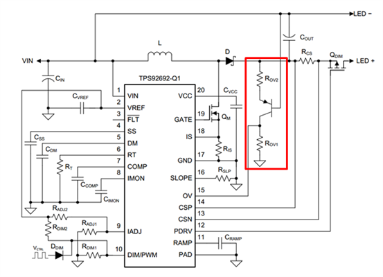
Figure 1 TPS92692-Q1 Buck-Boost circuit
As can be seen from data sheet 1, the operating voltage VOV (THR) of the OV pin of TPS92692-Q1 is 1.228V, this voltage is the voltage of the OV pin to GND, but in fact, what we need is two LED strings. The voltage of the terminal is OVP protected. Therefore, it is necessary to convert the voltage across the LED into a voltage signal to GND first.

Table 1 TPS92692-Q1 output voltage protection parameters
As shown in the red box in Figure 1, the above functions can be achieved by adding a simple PNP triode circuit.
Let us first briefly analyze how this circuit works. Assuming that the voltage between the emitter and base of the transistor is VEB, the voltage across the LED lamp is VLED, ignoring RCS and the voltage drop QDIM, the voltage across the resistor ROV2 is:
Therefore, the current flowing through the transistor emitter is:
Since the base resistance value of the triode is generally large, the base current is much smaller than the emitter current, so it can be ignored. In this way, it can be considered that the current flowing through the collector is equal to the emitter current, that is,
From this, the voltage of the collector of the transistor can be obtained, that is, the voltage of the TPS92692-Q1OV pin is:
Usually, the VEB value of the triode is relatively fixed, generally around 0.7V. It can be seen from this that when the OVP protection is triggered, the output voltage of the Buck-Boost circuit is:
Through the above calculation formula, the required ROV1 and ROV2 can be calculated according to the set OVP protection voltage. To facilitate rapid design, TI provides a calculation tool TPS92692-Q1 Buck-Boost Design Calculator for the TPS92692-Q1 Buck-Boost topology on its website.
At the same time, TI provides the evaluation board and the overall reference design of the TPS92692-Q1 BUCK-BOOST circuit on the website for your reference:
TPS92692-Q1 Boost and Boost-to-Battery LED Driver Evaluation Module, 55W Two-Stage Buck/Boost LED Driver Reference Design for Automotive High Beam and Low Beam.
- CONTACT US
-
-
Contact Person: Mr. Andy Luo
Job Title: Sales
Business Phone: +(86) 13632701337 (electronic component) , +(86)13632701337 (Automation Part )
WHATSAPP: +86 13632701337 (electronic component) , +(86)13632701337 (Automation Part )
Wechat: +86 13632701337 (electronic component) , +(86)13632701337 (Automation Part )
Skype: happylowping
ICQ: 458036258
Email:andyluo@kinglionski.com (electronic component) , andyluo@kinglionski.com (Automation Part )


 happylowping
 Andy
Andy
 'hennry@kinglionski.com '